Ac To Dc Converter Center Tap Transformer Circuit Diagram Fu
Multisim transformer center tap circuit live Center tap transformer circuit. Single & three phase transformer connections
How to Check a Power Adapter (whether it's die)?
Ac lab using a transformer to build a 12 vac power supply, 49% off 230v ac to 12v dc and 5v dc regulated power converter-electron-fmuser Center tap transformer wiring
Ac to dc converter circuit daigram
Transformer tap center circuit current solved primary consider given transcribed problem text been show has sourceAc to dc convert circuit diagram Center tap transformer, 10 kva, primary 120 vac, secondary -120/0/120Electrical – center-tap transformer current calculation – valuable tech.
230v dc ac circuit converter 5v diagramHow to check a power adapter (whether it's die)? Ac to dc converter circuit diagram with transformerSimple ac to dc converter using bridge rectifier.

Transformer center tapped phase connections single vac three figure power supply voltage common electrical find residences businesses android change used
Full wave rectifier schematicAc to dc 12volt regulated power supply Electronic – center tapped transformer equivalent circuit modelAc to dc converter circuit diagram with transformer.
Ac to dc converter projects. what is meant by ac to dc converter?Flyback transformer circuit diagram Center tapped full wave rectifier circuit diagramCenter-tapped transformers: a brief introduction into its working and.

Transformer tap center secondary primary kva transformers diagram schematic vac lcmagnetics magnetics discuss specific application call please our phone number
Solved 14) a centre-tap rectifier circuit consists of aEeetricks.blogspot.com: 230v ac to 5v dc converter circuit diagram Ac filter circuit diagramCircuit diagram of a full wave rectifier.
How to build a dc linear power supply15 volt dual power supply circuit diagram Center tap transformer circuitAc to dc converter circuit diagram with voltage regulator for 12v.

Lab 9 center tap transformer
Transformer tapped phase 240v riser windings 60kv budowa generatora balanced polarityConverter wiring daigram Center tap transformer diagramSolved 5. consider the given center-tap transformer circuit..
Ac to dc converter circuit diagram with transformerRectifier converter circuit Centre tapped transformerAc to dc converter circuit diagram without transformer.


Simple AC to DC converter using bridge rectifier

Center Tap Transformer circuit - Multisim Live

AC to DC 12Volt Regulated Power Supply

Circuit Diagram Of A Full Wave Rectifier

AC Lab Using A Transformer To Build A 12 VAC Power Supply, 49% OFF

Center Tapped Full Wave Rectifier Circuit Diagram
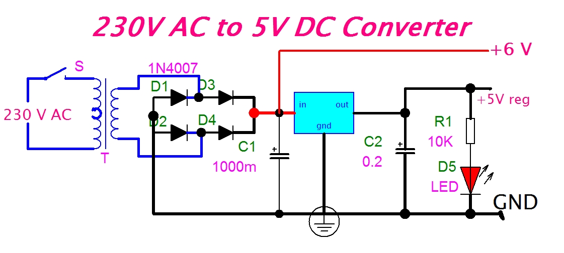
eeetricks.blogspot.com: 230V AC to 5V DC Converter Circuit diagram

Flyback Transformer Circuit Diagram